Sunday, 29 May 2011

LCD Tutorial 5

Modified character entry source code


The previous tutorial taught you how to implement the character mode and the code is very simple.  If you have not seen it, please check 'Tutorial Four' out before starting here.  This time, six function prototypes have been developed because it will save your time to use repetitive codes. The additional function prototypes are:

 character_mode   - It allows you to enter character in your LCD
 display_cursor      - Configures the underline, cursor and blink
 display_address   - Displays character within 2x16 character
  function_mode     - Configures number of line, bit and format
  table_lookup        - A table consists of A to Z and and numbers
  stop                       - No operation


Above the first column is the functional prototype which will be used in the code, the description on the 2nd column explains what each functional prototype actually does.  
 
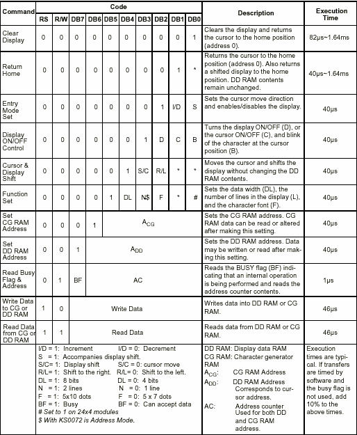
According to the source code below, the function_set has been configured so that the LCD module will use 2 lines, 8 bits and 5x7 format. The first character will display on $00. If you look the fourth line in the command mode table in tutorial, 0x08 would represent that cursor, underline and blink have been disabled. 

The character_mode function prototype automatically display 'HELLO WORLD' and it uses the table_lookup function prototype in order to find the hexadecimal number for each character. You can put different word between (' ') in the character_mode function prototype. Another display_cursor has been configured in order to enable underline, cursor and blink. Finally stop function prototype use 'while' loop which run endless.

 void main()
{
       // Configue LCD module into 2 lines, 8-Bits and 5x7 Pixels
        function_set();

        // Place character on $00
        display_address(0x80);

        // Blinking and underline cursor
        display_cursor(0x08);

        // Enter characters         character_mode(''HELLO WORLD");

        // Blinking and underline cursor
        display_cursor(0x0F);

        // Stop there
        stop();
}


Since there are only 16 character in each line, so it would not show the word with more than 16 letters. In the same source code, it has been devised to display the 17th character in the second line by using the display_cursor(0xC0); function prototype. Check it out in the character_mode function prototype. Here is an example, let apply 'DEOXYRIBONUCLEIC ACID' in the character_mode in the main program. You should see like this:


Wednesday, 25 May 2011

LCD Tutorial 4

"Hello World"


This tutorial shows you briefly how to enter character in your LCD module. You can enter number or alphabetic character so you need to look up another table called standard LCD character table. Let say we want to enter 'Hello' on second character in the 1st line.


A table above assists you to select the correct upper and lower 4 bits of data.  For example, look for upper 4 bits at the top of the table and the lower 4 bits of data can be found on the far left side. 

'H'            - 01001000 - 0x48
'E'            - 01100101 - 0x55
'L'             - 01101100 - 0z6C
'L'             - 01101100 - 0x6C
'O'            - 01101111 - 0x6F
SPACE   - 01100000 - 0x20
'W'           - 01010111 - 0x57
'O'            - 01100111 - 0x6F
'R'            - 01110010 - 0x72
'L'             - 01101100 - 0x6C
'D'            - 01100100 - 0x64
  
Note that pulse_e function prototype has been added in the main program.  It just activates enable on, few seconds delay then switch enable off.  Please check the codes for more information.

void main()
{
  // Set 8 bits, 2 lines, 5x7 Format  RW=0;
  RS=0;
  DATA=0x3B;
  pulse_e():

  // Display underline, cursor and blink 

  DATA=0x0F;
  pulse_e();
 

  // Display position 1st on 1 line 
  DATA=0x80;
  pulse_e(): 
 

  //Set RS High  
  RS=1; 
  // H  
  DATA=0x48;
  pulse_e();
 
 
  // e  DATA=0x65;
  pulse_e();

  // l

  DATA=0x6C;
  pulse_e();
  // l

  DATA=0x6C;
  pulse_e();
  // o
 
  DATA=0x20;
  pulse_e(); 
 

  //Set RS low  
  RS=0;
  // Display character on 1st position in 2nd line  
  DATA=0xC0;
  pulse_e(): 
 

  //Set RS High  
  RS=1;
  // W  
  DATA=0x6F;
  pulse_e(); 

  // o  
  DATA=0x72;
  pulse_e(); 
 
  // r  
  DATA=0x6C;
  pulse_e(); 
 

  // d 
  DATA=0x64;
  pulse_e();
 

  //Set RS low  
  RS=0;
}

Tuesday, 24 May 2011

LCD Tutorial 3

Display Address, Display cursor, blink and underline


2 Lines & 16 Character - Address

Since we are using 2x16 LCD module. 2 and 16 are lines and characters respectively. Each character has unique address as shown above. Maybe you want to start to start from seventh cursor (0x07) instead of first cursor (0x00). At the bottom line of the command control codes, you would see a lot of A. Well A stands for Address. You need to enter 0x87 after = in the fifth line. Then repeat the displaying codes in the second tutorials:

This time, you are going to learn how to display cursor, blink and underline. It is fairly simple procedure like what you have learned in your previous tutorial. Again you need to look up the command control codes table at fourth row, D, U and B represents display, underline and blink respectively. The binary number would be '1000' or '0x08' in hexadecimal number. Now you need to use the similar code as described above and modify line five by putting 0x08. Compile the software and upload the Hex files in your microcontroller chip and give it a test. Your LCD display should like this:

void main()
{
    // Set 8 bits, Line 2 and 5x7 format
    RW=0;
    RS=0;
    DATA=0x3B;
    ENABLE=1;
    De
lay_Loop(5);
    ENABLE=0;
    // Display position 7th on 1 line
    DATA=0x87;
    ENABLE=1;
    Delay_Loop(5);
    ENABLE=0;

    // Display underline, cursor and blink
     DATA=0x0F;
     ENABLE=1;
     Delay_Loop(5);
     ENABLE=0;
}


Monday, 23 May 2011

LCD Tutorial - Documents for interfacing LCD with a microcontroller chip

Found two good documents to help you to learn about interfacing LCD with a microcontroller especially PIC chips..........

Download LCD Document 1
Download LCD Document 2

LCD Tutorial 2

Tutorial 2 - Command mode (Function Set)


Before you power the circuit up, please take a microcontroller chip out of the circuit. You should see the black dim light appears on the first line. If you cannot see it, adjust the potentiometer with a screw in order to make the line more notiable. If nothing happens, you need to check the layout right and make sure that the you connect the LCD module properly.


Since you are going to control the LCD module with 8 bits and use 2 lines and 5x7 format.. According to the sixth row of command control codes table, you need to configure the function set by setting hexadecimal number as 0x3B. Please be aware that 'x' represents don't care so in this case you are going to use 1 instead of 0.

In your first example code, you need to set both RS and RW to logic zero. Then you set the enable high, generate delay for microseconds and turn the Enable off. Remember that from Port 3.0 to 3.2 are used as RW, RS and Enable respectively while the 8 bits are used in Port 0 which denotes as DATA.

void main()
{
       // Set 8 bits, Line 2 and 5x7 format 
        RW=0;
        RS=0;
        DATA=0x3B;
        ENABLE=1;
        Delay_Loop(5);
        ENABLE=0;

}


Hey presto, the LCD module will automatically display 2 lines. Is it pretty simple stuff eh?


LCD Tutorial 1

                     Tutorial 1 - 2x16 LCD module's hardware and pin layout's Description


You need:

  • 40 ZIF Socket
  • AT89C51
  • 12MHz Crystal Oscillator
  • Two 33pF ceramic capacitors
  • 47uF Electrolytic capacitor
  • 10k resistor
  • 16 pin header 2.54" (It can be fixed with LCD module for inserting into the breadboard)
  • 4.7k Potentiometer
  • Core wire (Red, Black, Blue and Yellow) 
A breadboard layout of AT89C51 chip and a LCD module

A schematic of AT89C51 and LCD module