Tutorial 1 - 2x16 LCD module's hardware and pin layout's Description


You need:
A breadboard layout of AT89C51 chip and a LCD module


You need:
- 40 ZIF Socket
- AT89C51
- 12MHz Crystal Oscillator
- Two 33pF ceramic capacitors
- 47uF Electrolytic capacitor
- 10k resistor
- 16 pin header 2.54" (It can be fixed with LCD module for inserting into the breadboard)
- 4.7k Potentiometer
- Core wire (Red, Black, Blue and Yellow)


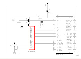
A schematic of AT89C51 and LCD module
No comments:
Post a Comment